Studie on acoustic impedance-matching layer
A quick outline
In non-destructive testing (NDT), ultrasound imaging, the inspection goal is, most of the time, to transmit as much energy as possible towards the inspected specimen. If there are multiple media between the emitter (transducer) and the focus point, energy is dissipated through different forms. One way wave-front energy is “lost” is through reflection at intermediary refraction profiles. The amount of energy “lost” could be estimated through transmission and reflection coefficients. Particularly, when the incident wave is normal, the transmitted pressure wave amplitude can be calculated using acoustic-impedance-based formulas. Although these coefficients are expressed in terms of pressure/pressure amplitude (not energy or intensity), they still serve as a good indicator of whether transmission is effective.
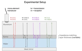
In this project, I proposed a mini-simulation to explore how the pressure wave amplitude changes at the aluminum-water interface. I considered three propagation paths, highlighted in different colors in the banner image. Then, by summing all components, I computed an expected received amplitude.
If there is only the aluminium-water refraction profile, most of the energy is reflected, thus not transmitted towards the mirror (which would be our specimen). By introducing an acoustic matching layer, I computed the new amplitude, and the video shows that the loss is highly mitigated. Besides amplitude increase through acoustic impedance matching, amplitude can also be increased by thin-layer constructive interference. In the video, a variable-thickness acoustic matching layer and the peak amplitude are shown. It is clear that when the layer reaches a quarter of the wavelength, constructive interference and maximum amplitude are achieved.
Video:
